Appendix: Electron Microscopes
The microscope you're using is a brightfield light microscope, the
most common type. There are many others, and their operating peculiarities,
advantages, and disadvantages, are too long to go into detail. If your interest
has been piqued, I suggest reading any one of the numerous books available on
microscopy. For a longer treatment of this subject,
click here.
There are, however, two other microscopes you should have at least a nodding
familiarity with since it's likely that in the course of your studies and/or
practice you will encounter images made with either the transmission electron
microscope or the scanning electron microscope. Aside from size and
cost, one major difference between these and the ordinary light microscope is
that the specimen must be examined under a vacuum; electron beams are stopped
by gas molecules.
The Transmission EM
 The transmission electron microscope (TEM) dates from 1931 in its crudest form, and was refined in the late 1930's by a research team at the university of Toronto, who built the first practical TEM in 1938. One member of that team, Dr James Hillier (right) has come to be regarded as the father of the modern TEM; his invention of a practical electronic lens made it possible. The development of the TEM received a great boost from advances in electronics technology during World war 2, and after the war the radio Corporation of America marketed the first commercially-available TEM's, the "EMU" series. The TEM made it possible to envision and study objects orders of magnitude smaller than any light microscope could show, and its availability literally caused upheavals in the life sciences as new discoveries became almost daily events. Virtually everything taught to students today as "basic information" is based on the information gained with TEMs like the one at right, between 1945 and 1965. The TEM is quite the most important advance in technology in the life sciences of the 20th Century, on a par with Mendel's discovery of the laws of genetics.
A TEM operates
very much like the brightfield light microscope does. However, in the TEM the "light" is actually a beam of electrons, produced by energizing a
tungsten filament with high voltage, so that electrons come off it. The condenser
lens focuses the beam and maintains it in a stable position.
Lenses
The TEM's lenses are not made of glass: they are, rather, electromagnetic
coils. The charged particles composing electron beams can easily be focused
using magnetic fields, and much of the circuitry in a TEM is dedicated
to producing stable and reproducible lens currents.
A TEM has condenser and objective lenses, just as the light microscope
does; but instead of an ocular, the primary image is passed to an imaging
system which is the functional equivalent.
The imaging system consists of another lens, the projector, which
casts the image onto a flat metal plate coated with a phosphorescent material,
much like the coating on a TV screen. When an electron hits this coating,
it causes the coating to glow. In those areas of the viewing screen where
many electrons hit, the glow is bright; in others it's dim to blank, in
proportion. The image created on the plate is really a highly detailed
shadow of the specimen that is in the beam. It's sometimes called a "mass
density map" because it reflects the different densities in different parts
of the specimen.
Below the viewing screen is a camera chamber, holding a sheet of film.
The screen can be moved out of the way to expose the film to make a permanent
record of the image (photographic emulsions are sensitive to electrons). In more modern instruments the old phosphorescent vieing screen and the photographic plates have been replaced with electron-sensitive chips and digital image recording devices.
Contrast in the TEM
In a light microscope, the image is seen in color, and contrast is achieved
by staining the specimen with different dyes. In the TEM, since there is
no light, and since the electron beam has only a single wavelength, color
has no meaning. Contrast is achieved instead by introducing variable density
in the different parts of the specimen. Instead of dyes, "staining" for
the TEM depends on the impregnation of the tissue with heavy metal atoms,
typically uranium and lead. These serve to scatter the electrons passing
through the specimen, so that areas with low levels of impregnation produce
bright regions on the screen, and heavily impregnated areas produce dark
ones (the electrons can't get through). All shades of gray are represented
by partial transmission.
The Scanning EM
The scanning electron microscope (SEM) is a relatively recent invention.
Although the theoretical principles were quite well understood more than
50 years ago, the realization of the SEM as a practical device required
advances in electronics far beyond the frontiers of the early 1930's. The
Second World War gave a considerable impetus to the development of related
technology, as did the 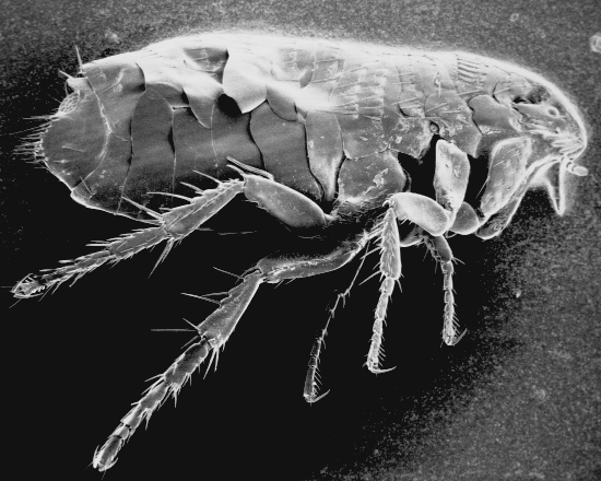 massive expansion of the television industry in
the post-war period. Nevertheless, it was not until the early 1960's that
SEM's were commercially available, and
even then their application to the life sciences was limited: the first
commercially supplied SEM was sold to a paper company!
Today they find their greatest use in the manufacture of microchips.
massive expansion of the television industry in
the post-war period. Nevertheless, it was not until the early 1960's that
SEM's were commercially available, and
even then their application to the life sciences was limited: the first
commercially supplied SEM was sold to a paper company!
Today they find their greatest use in the manufacture of microchips.
The SEM is unmatchable in its utility for examining surface structure, which is why chip producers use them. The SEM creates a "3 dimensional" image such as the one of the flea shown at left.
All SEM's are constructed with a specimen stage that permits the object
under scan to be rotated, tilted, and traversed from side to side and back
and forth. Thus, unlike a conventional microscope, it's possible to view
almost all parts of the specimen by twisting it around in various ways
to get a different vantage point. This permits an "observer" to examine
any point on a surface, so long as a straight line can be drawn between
that point and the "observer," whose virtual position is at the top of
the microscope, looking "down" at the specimen.
Parts of an SEM
The SEM has three principal components: the control consolecontains circuitry to maintain stable lens currents, evacuate the specimen
chamber, produce a beam of electrons, and so on; the display output
produces the image in the form of a television type picture on a cathode
ray tube (CRT); and the column contains the specimen and the means
of observing it.
During observation, the column is under vacuum, and the specimen is
at the bottom. At the top is the electron source, a hair-thin, V-shaped
filament of fine tungsten wire. This is heated to incandescence in the evacuated
column by passing a high voltage, low amperage current through
it. It glows, exactly as does the filament in a light bulb,
and electrons boiling off it are channeled down the column as
a tightly coherent beam, aimed directly at the specimen. The cohesiveness
and direction of the beam is controlled by electromagnetic lenses, hollow
coils of fine wire whose magnetic fields can be controlled from the console
to provide for focusing and magnification changes.
As the name of the instrument implies, the beam is not static: it "scans"
the specimen. The beam moves over the specimen from one
side to the other, drops down one line, then returns and completes another
sweep at the lower level. When the last sweep is completed, the beam returns
to the start point, and begins again to scan, back and forth, down, and
repeat.
The scan rate is controlled by the console circuitry.
When a beam of electrons impinges on an object, it knocks other electrons
loose from the object itself. These secondary electrons scatter
in directions determined by the angle of incidence of the beam, and by
the surface topography of the specimen.
Secondary electrons are detected by inserting a
detector near the specimen. The detector produces a variable
voltage output; the more secondary electrons it detects, the greater will
be the voltage generated. This signal, in the form
of a fluctuating voltage, is used to modulate the output of an electron gun on a cathode
ray tube (CRT). When the signal is high, the display CRT's electron gun
produces large numbers of electrons, and when it's low, small numbers.
The beam generated in the CRT thus corresponds in its output to the secondary
electron emissions of the specimen.
The SEM Image Display
The CRT beam is not static, either. It sweeps back and forth across
the face of the tube (exactly as in a TV set, which is what a display CRT
actually is) and its sweep is synchronized with that of the electron beam
in the column. When the column beam knocks off large numbers of secondary
electrons from some point on the specimen, the CRT beam produces a bright
spot on the viewing screen. Conversely, small numbers of electrons produce
low CRT beam output, and a dark point on the viewing screen. Thus the SEM
image is really an analog of what is going on inside the column; it's constructed,
point-by-point and line-by-line, based on the information supplied to the
CRT by the detector circuitry.
The same process is used to produce a television image from a transmitted
signal, and an SEM can be considered as a sort of gigantic light bulb hooked
into a TV set.
Similarities and Differences in EMs
The two types of electron microscope have some similarities and some
differences. They are similar in that they both examine specimens under
vacuum; but they differ in how the images are produced. The TEM, as the
name implies, actually relies on the transmission of the beam through the
specimen: the direct physical interposition of the specimen into the beam
is necessary to produce the image. The SEM, on the other hand, can examine
specimens much too thick for the beam to pass through, and its image is
produced electronically by modulation of the CRT output based on the detector
signal. Therefore, no physical connection exists between the
object and its image; the column can be in one room and the display CRT
in another. So long as the electronics are intact, the image can be produced.
Furthermore, contrast and brightness can be adjusted, as on a TV set, with
console controls. Photographic records are made by actually making images
of the CRT screen. Alternatively, the output can be fed to a videotape
recorder.

Close this Window